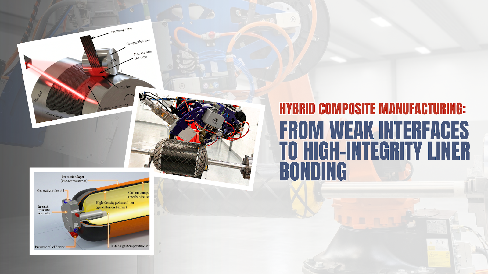
Interfacial Integrity in Robotic Over-Printing: Joining Continuous Fiber Composites to Prefabricated Liners
A Technical Review of Hybrid Manufacturing Challenges at the Composite-Liner Interface
Abstract
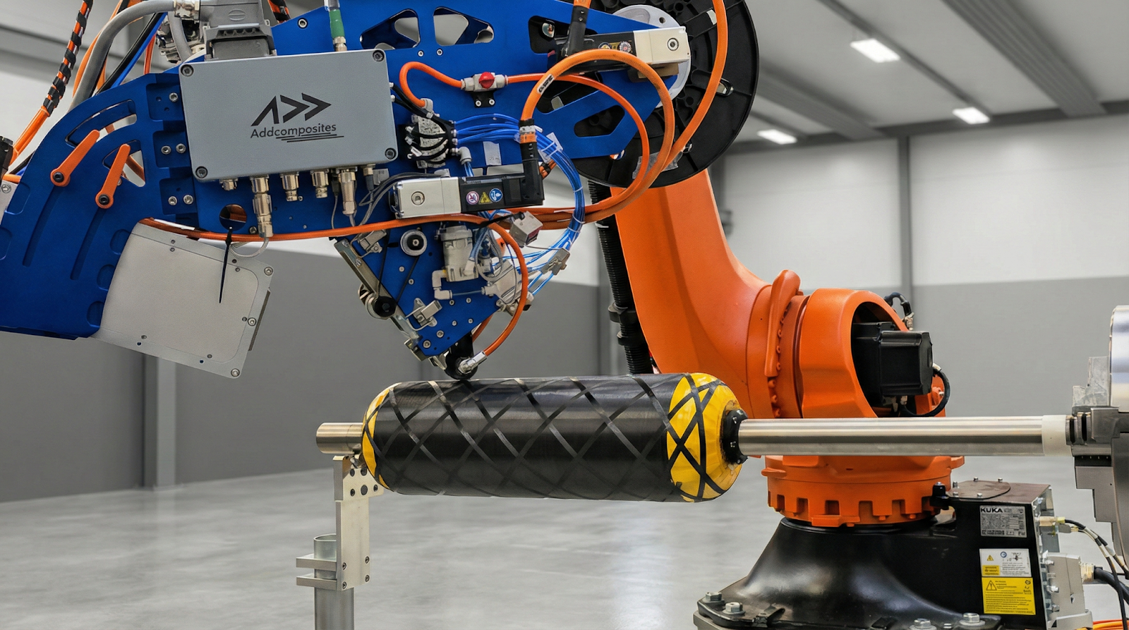
The transition from conventional autoclave-cured composite manufacturing to robotic over-printing of continuous fiber thermoplastics onto prefabricated polymer liners represents a paradigm shift in pressure vessel and structural reinforcement production. This review examines the critical technical challenges inherent in "hybrid manufacturing"—specifically, the deposition of hot composite tape (temperatures exceeding 300°C for engineering thermoplastics) onto cold, pre-made liners such as those found in Type IV/V composite overwrapped pressure vessels (COPVs) and automotive structural reinforcements.
The analysis focuses strictly on the interface: adhesion mechanisms governing bond formation, surface preparation technologies ranging from plasma treatment to laser ablation, and thermal management strategies to prevent liner collapse or burn-through. Quantitative data on lap shear strength improvements (up to 8.35× enhancement with optimized laser treatment), coefficient of thermal expansion (CTE) mismatches (carbon fiber at -1.5 to +1.5 ppm/°C versus HDPE at 100-200 ppm/°C), and hydrogen permeability rates are synthesized to provide engineers with actionable design guidelines for robust interfacial bonding.
1. The Interface Problem: Thermal Incompatibility at the Bonding Frontier
1.1 Fundamental Challenge
The deposition of molten continuous fiber thermoplastic tape onto a cold polymer substrate creates a thermal shock scenario that fundamentally challenges interfacial integrity. In thermoplastic tape winding (TTW) and automated fiber placement (AFP), the incoming prepreg tape must reach temperatures sufficient for matrix flow and molecular interdiffusion—typically 280-400°C for engineering thermoplastics like PEEK, PEKK, or carbon fiber-reinforced polyamide. Meanwhile, the prefabricated liner, whether high-density polyethylene (HDPE) or polyamide (PA6/PA11), maintains ambient or moderately elevated temperatures.
This temperature differential creates several competing failure mechanisms:
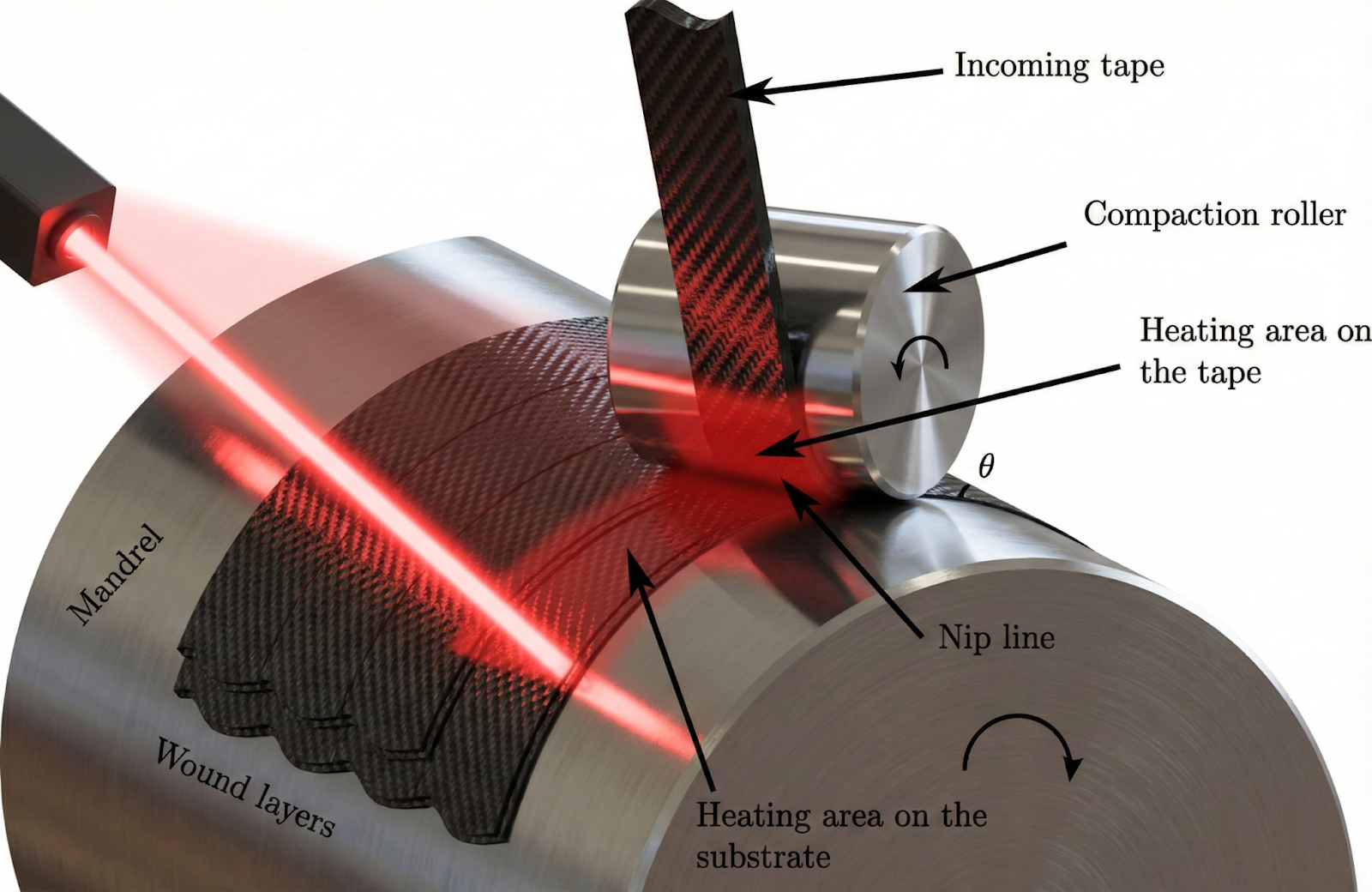
Thermal Gradient at the Nip Point During Over-Printing
Cross-sectional view showing temperature distribution during thermoplastic tape deposition onto a polymer liner. Illustrates the steep thermal gradient from molten tape (~350°C) through the interface to the cool liner substrate (~25-80°C), with heat flux vectors and consolidation roller position.
Thermoplastic Tape Winding Process
Temperature distribution through the compaction zone
1.2 The Bonding Mechanism: Intimate Contact and Autohesion
Successful fusion bonding between the incoming tape and substrate requires satisfaction of two sequential conditions:
The degree of healing Dh follows: Dh = (t/tw)1/4, where t is contact time and tw is the reptation time (temperature-dependent).
For dissimilar materials (e.g., CF/PEEK tape onto PA6 liner), true autohesion is impossible; bonding instead relies on mechanical interlocking, van der Waals interactions, and potential chemical bonding at functionalized surfaces.
1.3 Failure Statistics in COPV Applications
The criticality of the liner-composite interface is underscored by failure statistics from composite overwrapped pressure vessel applications:
- Liner failure is the second leading cause of COPV failure after composite damage
- Interface debonding contributes to liner collapse during rapid depressurization cycles
- The 2016 SpaceX Falcon 9 pad explosion was attributed to failure of a COPV, where frozen solid oxygen accumulated between the aluminum liner and composite overwrap, demonstrating the catastrophic consequences of interface defects
2. Surface Activation Technologies
The inherently low surface energy of polyolefins (HDPE: 28-30 mN/m) and the semi-crystalline nature of engineering polymers create barriers to adhesive bonding. Surface activation technologies aim to increase surface energy, introduce polar functional groups, and create mechanical interlocking features.
2.1 Atmospheric Plasma Treatment
Plasma treatment represents the most widely adopted surface activation technology for thermoplastic liner materials, offering non-contact processing and integration into continuous manufacturing lines.
Mechanism:
- Interaction of plasma species (charged particles, molecular radicals, excited species) with the polymer surface
- Introduction of oxygen-containing functional groups (C-O, C=O, O-C=O, O-H)
- Surface oxidation increases surface energy from ~28 mN/m to >50 mN/m
Quantitative Results:
| Material | Contact Angle Reduction | Surface Energy Increase | Shear Strength Gain |
|---|---|---|---|
| HDPE | 47.3° decrease | 28 → >50 mN/m | 2-3× |
| PA12 | 42.6° decrease | — | 2-4× |
| PA6 | 50.1° decrease | — | Up to 4× |
| PP | Similar to HDPE | 28 → 105+ dynes/cm | 2× |
Critical Limitation—Aging Effect:
The plasma treatment effect is not permanent. Contact angle measurements show pronounced relaxation (aging) after treatment, with surface energy declining significantly within hours to days as polymer chains reorganize and polar groups become buried. This necessitates immediate bonding after plasma treatment or use of protective primers.
Plasma Surface Treatment Mechanism
Surface activation for improved adhesion bonding
2.2 Mechanical Abrasion: Grit Blasting and Sanding
Mechanical surface preparation creates topographical features for mechanical interlocking and removes surface contaminants.
Grit Blasting Results (CFRP Adherends):
- Peel-ply + grit blasting: Highest average roughness (7.35 μm), highest surface energy (49.1 mJ/m²)
- Manual sanding: Effective but operator-dependent
- Random sanding direction: Highest shear strength reported
Critical Consideration for Thermoplastics:
Unlike thermosets, where abrasion breaks and opens cross-linked polymer chains to increase reactivity, thermoplastic polymers are not locked into rigid networks. Abrasion alone may not provide lasting surface activation—energetic treatments (plasma, laser) are often required in combination.
2.3 Laser Surface Treatment
Laser ablation offers precise, non-contact surface modification with the ability to create controlled micro-scale features.
Nanosecond Pulsed Laser Treatment for PA11-CFRP Interfaces:
A breakthrough study demonstrated the effectiveness of nanosecond pulsed laser treatment for enhancing bonding between PA11 liners and CFRP in Type IV hydrogen storage vessels:
| Parameter | Untreated | Laser-Treated | Improvement |
|---|---|---|---|
| CDP Strength (N·mm/mm) | ~5.1 | 24.1 | 4.74× |
| FWT Strength (MPa) | ~0.29 | 2.43 | 8.35× |
Mechanism: Formation of periodic grooves on the PA11 surface increases roughness and mechanical interlocking area. UV wavelengths (355 nm) additionally introduce polar functional groups (O-C=O, O-O) through photo-chemical bond breaking rather than purely thermal ablation.
Combined Laser-Plasma Treatment (2025 Results): Synergistic treatment achieved fatigue cycle improvements of 11.8× at 45% stress level and 20.4× at 90% stress level
Laser-Induced Surface Microstructure on PA11
Nanosecond pulsed laser treatment creates periodic groove structures for mechanical interlocking with CFRP matrix
Source: Adapted from nanosecond laser treatment studies [11] DOI: 10.1016/j.ijhydene.2023.12.304
2.4 Chemical Primers and Coupling Agents
Silane coupling agents provide chemical bridging between dissimilar materials:
Mechanism:
- Hydrolyzable groups (typically alkoxy: -OCH₃, -OC₂H₅) react with hydroxyl groups on substrates
- Organic functional groups (amino, mercapto, epoxy) react with polymer matrices
- Creates covalent "adhesive bridge" at the interface
Performance Data:
- Plasma-treated CF thermoplastic + mercapto silane monolayer: 27 MPa shear stress (versus 10 MPa untreated, 22 MPa plasma-only)
- Dipodal silanes: Up to 10⁵× greater hydrolysis resistance for primer applications
- Aminosilane coupling agents: Achieved 1.53 MPa adhesive strength in thermal protection coatings at 13 wt% loading
2.5 Comparative Surface Treatment Performance
Lap Shear Strength by Surface Treatment Method
| Treatment | Substrate | Adhesive/Bond Type | Lap Shear (MPa) | Failure Mode |
|---|---|---|---|---|
| Untreated | HDPE | Structural adhesive | ~3-5 | Adhesive (interface) |
| Plasma (air) | HDPE | Structural adhesive | 10-15 | Mixed |
| Plasma (air) | PA6 | Structural adhesive | 20-22 | Cohesive (adhesive) |
| Plasma + Silane | CF/thermoplastic | Direct fusion | 27 | Cohesive (substrate) |
| Grit blast | CFRP | Epoxy adhesive | 15-20 | Mixed |
| Peel-ply + grit | CFRP | Epoxy adhesive | 20-25 | Cohesive |
| Laser (CO₂) | CFRP | Adhesive | 14.3 | — |
| Laser (ns pulsed) | PA11 | CFRP direct | 2.43 (FWT) | — |
Note: Cohesive failure in the substrate or adhesive indicates the interface is no longer the weakest link—the desired outcome.
3. Thermal Bonding Windows
3.1 Critical Temperature Thresholds
Successful fusion bonding requires maintaining the interface within a narrow "bonding window" defined by the thermal properties of both materials:
Lower Bound:
Interface temperature must exceed the glass transition temperature (Tg) of the liner material to enable molecular mobility and wetting. For semi-crystalline polymers, temperatures approaching or exceeding the melt temperature (Tm) may be required for optimal bonding.
Upper Bound:
Liner bulk temperature must remain below the threshold for:
- Structural collapse under internal pressure or self-weight
- Excessive thickness reduction from creep
- Thermal degradation or oxidation
Thermal Properties of Common Liner Materials
| Material | Tg (°C) | Tm (°C) | Max Service Temp (°C) | Critical Notes |
|---|---|---|---|---|
| HDPE | -110 | 130-135 | 80-100 | Very low Tg; always above glass transition at RT |
| PA6 | 47-71* | 220 | 150-180 | Tg moisture-dependent (*dry: ~71°C, wet: ~0°C) |
| PA11 | 42-46 | 185-190 | 130-150 | Lower Tm than PA6 |
| PA12 | 37-42 | 175-180 | 120-140 | Good chemical resistance |
| PP | -10 to 0 | 160-165 | 100-120 | Low cost option |
Composite Tape Processing Temperatures:
| Tape Material | Processing Temp (°C) | Nip Point Target (°C) |
|---|---|---|
| CF/PEEK | 380-400 | 350-380 |
| CF/PEKK | 340-380 | 320-360 |
| CF/PA6 | 250-280 | 220-260 |
| CF/PA12 | 230-260 | 200-240 |
| CF/PP | 180-220 | 170-200 |
3.2 Thermal Management Strategies
Liner Pre-Heating:
Elevating liner temperature reduces the thermal gradient and shock severity while promoting better wetting:
- HDPE liners: Pre-heat to 60-80°C (below Tm with safety margin)
- PA liners: Pre-heat to 80-120°C
- Method: Infrared heaters, hot air circulation, heated mandrels
Layup Speed Reduction:
Slower deposition allows more time for heat conduction into the liner, enabling surface temperatures to equilibrate:
- Trade-off: Reduced productivity
- Typical adjustment: 50-70% speed for first ply versus steady-state
Laser/Heat Source Power Modulation:
Closed-loop temperature control using pyrometry enables real-time adjustment:
- Hoop versus axial layups require different power settings due to varying dwell times
- First-ply deposition onto dissimilar liner requires reduced power to prevent burn-through
Process Window for CF/PA6 Tape onto PA6 Liner
Temperature-speed operating envelope for thermoplastic tape winding
3.3 Liner Compatibility Requirements
For direct fusion bonding (without intermediate adhesive), the liner and tape matrix should ideally share the same base polymer to enable true autohesion:
- CF/PA6 tape → PA6 liner: Compatible (molecular interdiffusion possible)
- CF/PEEK tape → HDPE liner: Incompatible (no interdiffusion; relies on mechanical interlocking and surface functionalization)
When material systems are incompatible, surface activation becomes critical, and bond strength expectations must be adjusted accordingly.
4. Residual Stress and Warpage: CTE Mismatch Effects
4.1 The CTE Mismatch Problem
The coefficient of thermal expansion mismatch between carbon fiber composite overwrap and polymer liner materials represents a fundamental source of residual stress accumulation.
Coefficient of Thermal Expansion Comparison
| Material | CTE Longitudinal (ppm/°C) | CTE Transverse (ppm/°C) | Notes |
|---|---|---|---|
| Carbon Fiber (raw) | -1.5 to +1.0 | 7-30 | Negative in fiber direction |
| UD CFRP (fiber dir) | -0.5 to +1.5 | 30-57 | Fiber-dominated |
| Woven CFRP panel | ~1.5 | ~5-15 | Balanced weave |
| CF/PEEK | ~0 to +2 | 25-40 | High-performance |
| HDPE | 100-200 | 100-200 | Isotropic |
| PA6 | 70-130 | 70-130 | Isotropic |
| PA6 + 60% GF | ~50 | ~50 | Reduced by reinforcement |
| PA6 + Nanocellulose | ~24 | ~24 | Comparable to aluminum |
4.2 Residual Stress Mechanisms
Residual stresses develop during cooling from processing temperature to ambient conditions:
4.3 Consequences for Pressure Vessel Applications
Liner Collapse Mechanism:
During rapid depressurization of Type IV hydrogen vessels, the composite overwrap (with lower CTE and higher stiffness) constrains the liner's thermal contraction less than its pressure-induced contraction. This creates a pressure differential at the liner-CFRP interface:
- High internal pressure expands liner into tight contact with composite
- Rapid depressurization: Internal pressure drops faster than liner can contract
- Liner buckles inward into the gap between its equilibrium position and the composite
Contributing Factors:
- Higher maximum hydrogen pressure → greater pressure differential
- Faster depressurization rate → less time for equilibration
- Lower residual pressure → larger pressure difference
- Weak interfacial bonding → easier debonding initiation
CTE Mismatch and Residual Stress Distribution
Thermal strain accommodation at the liner-composite interface during cooling
Interfacial Shear Stress Distribution (τ)
Interfacial Shear Stress
Develops at the liner-composite interface due to differential thermal contraction. Maximum at center, reduces toward edges where stress concentration occurs.
Liner Compression
Liner experiences compressive hoop stress as it's constrained from free thermal contraction by the stiffer composite overwrap structure.
Edge Effects
Stress concentration at interface edges can initiate delamination. Critical design consideration for hydrogen tank liner integrity.
Source: Based on residual stress modeling [15, 16] DOI: 10.1002/pc.25934
4.4 Mitigation Strategies
Material Selection
Use liner materials with lower CTE (reinforced PA > neat PA > HDPE). Consider nanofiller reinforcement to reduce liner CTE toward composite values.
Process Optimization
Controlled cooling rates to allow stress relaxation. Staged cooling with intermediate holds near Tg. Fiber prestressing to offset thermal contraction.
Design Considerations
Symmetric layups where possible. Gradual transition regions at dome-cylinder junctions. Avoid sharp thickness changes.
5. Case Study Analysis
5.1 Hydrogen Composite Overwrapped Pressure Vessels (COPVs)
Application Context: Type IV and emerging Type V COPVs are critical enablers for hydrogen mobility, requiring storage at 350-700 bar with minimal weight penalty. The interface between polymer liner and carbon fiber composite overwrap directly impacts:
- Structural integrity under cyclic pressurization
- Hydrogen permeability and leakage rates
- Resistance to liner collapse during rapid refueling/discharge
Liner Material Selection:
| Property | HDPE | PA6 | PA11 | Best for H₂ |
|---|---|---|---|---|
| H₂ Permeability | Highest | Lower | Lower | PA6 |
| Cost | Lowest | Medium | Higher | HDPE |
| CTE Match | Poor | Fair | Fair | PA6 |
| Moisture Sensitivity | None | High | Low | HDPE, PA11 |
Hydrogen Permeability Data:
At 288 K and 70 MPa:
- PA6 exhibits the strongest hydrogen permeation resistance
- PA11 has approximately 12.5% higher diffusion coefficient than PA6
- HDPE has approximately 350% higher diffusion coefficient than PA6
The GTR 13 international standard specifies maximum allowable hydrogen permeation rate of 46 Ncm³·h⁻¹·L⁻¹ at 1.15× nominal working pressure and 55°C.
Interface Enhancement Case Study:
The nanosecond pulsed laser treatment study demonstrated that optimized surface preparation can dramatically improve interface integrity:
- Problem: Weak PA11-CFRP bonding contributes to liner collapse risk
- Solution: Laser texturing at 400 mm/s, 20 kHz, 12.7 W
- Result: 8.35× improvement in flatwise tensile strength
- Implication: Reduced risk of interface debonding during pressure cycling
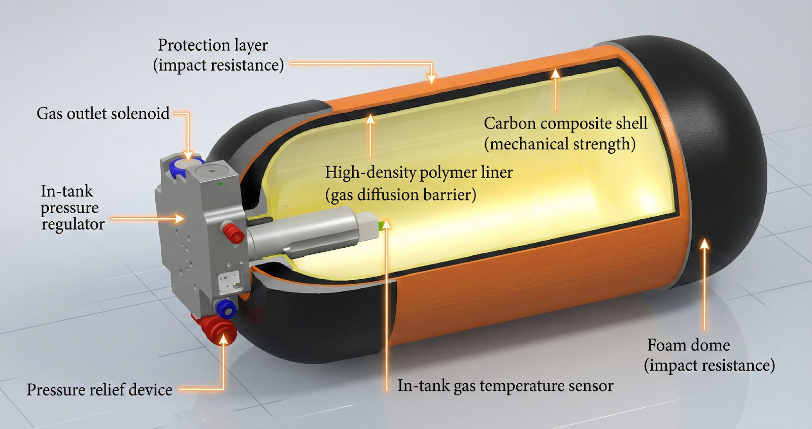
Figure 6: Type IV COPV Cross-Section and Interface Detail
Cross-sectional view of Type IV COPV showing (a) overall vessel construction with polymer liner, composite overwrap, and metallic bosses, and (b) detail of liner-composite interface with surface treatment features.
Type IV COPV Structure and Interface Design
Composite Overwrapped Pressure Vessel for hydrogen storage applications
5.2 Automotive Structural Reinforcement: B-Pillar Over-Molding
Application Context: Automotive B-pillars (center pillars) are critical structural members for side-impact protection. Hybrid manufacturing approaches combine steel or aluminum stampings with composite reinforcements to achieve weight reduction while meeting crashworthiness requirements.
Hybrid Molding Approach:
- Organosheet (e.g., 47 vol-% glass fabric/PA6) is compression-molded as carrier
- Short-fiber reinforced polymer (e.g., 30 wt-% glass/PA6/6) is injection over-molded for ribs
- Expanding adhesive (epoxy-based foam) bonds composite to metal structure
Weight Reduction Achieved: 67.37% compared to steel reinforcements while maintaining crashworthiness requirements
Interface Considerations:
- PA6 carrier + PA6 overmold: Same-polymer system enables fusion bonding
- Composite-metal interface: Requires adhesive bonding with surface preparation
- Expanding adhesive: Accommodates tolerance variations and fills gaps
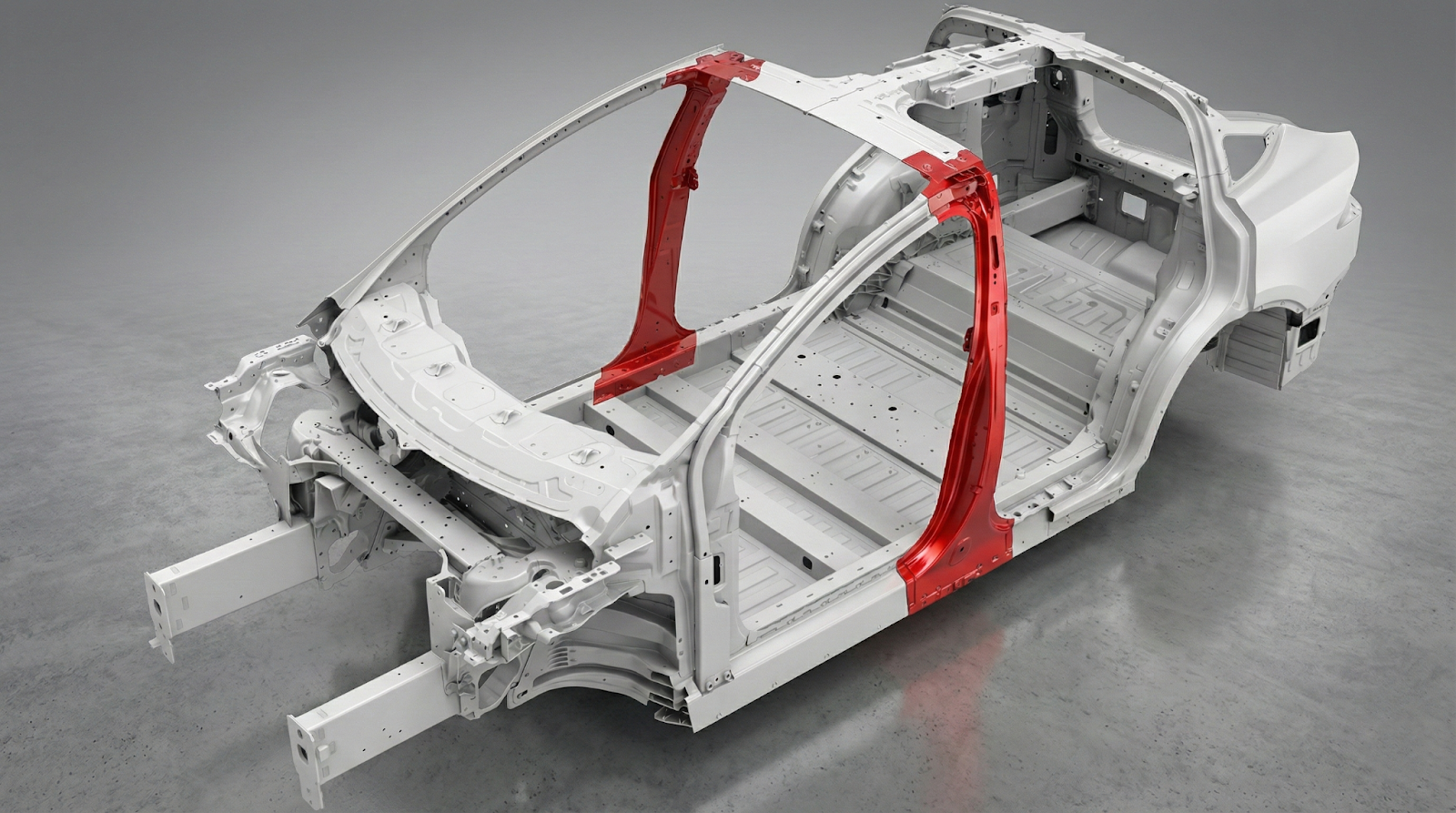
Figure 7: Automotive B-Pillar Hybrid Structure
Exploded view of hybrid B-pillar construction showing steel outer panel, composite reinforcement insert (compression-molded organosheet + injection over-molded ribs), and adhesive interface layer.
Hybrid Automotive Panel Structure
Steel-composite hybrid construction with over-molded reinforcement ribs
(30% GF/PA6/6)
Molding
molding
Application
Bonding
5.3 Comparative Failure Mode Analysis
Understanding whether failures occur at the interface (adhesive failure) or within the substrate (cohesive failure) provides critical feedback on surface treatment effectiveness:
Failure Mode Analysis by Surface Treatment
| Treatment | Typical Failure Mode | Interpretation | Action Required |
|---|---|---|---|
| Untreated | Adhesive (interface) | Interface is weak link | Surface activation needed |
| Plasma (short) | Mixed | Partial improvement | Extend treatment time |
| Plasma (optimized) | Cohesive (adhesive layer) | Interface stronger than adhesive | — |
| Grit blast only | Mixed to adhesive | Limited chemical activation | Add plasma or primer |
| Laser + Plasma | Cohesive (substrate) | Optimal—substrate is weak link | Treatment successful |
Key Insight:
Achieving cohesive failure in the substrate indicates the interface is no longer the weakest link in the system. This is the target outcome for surface treatment optimization.
6. Future Directions and Research Gaps
6.1 Identified Research Gaps
Long-Term Durability Data
Most surface treatment studies report initial bond strength; fatigue and aging data under realistic service conditions (temperature cycling, hydrogen exposure, moisture) remain limited.
In-Situ Process Monitoring
Real-time quality assurance methods for interface bonding during robotic over-printing are underdeveloped. Thermography and acoustic methods show promise but require validation.
Type V Vessel Development
Linerless composite pressure vessels eliminate the liner-overwrap interface entirely, representing a paradigm shift. However, resin permeability and damage tolerance challenges remain.
Multi-Material Gradient Interfaces
Functionally graded interfaces that transition gradually from liner to composite properties could reduce stress concentrations but are not yet manufacturable at scale.
Standardized Testing Protocols
Lack of standardized test methods specifically for liner-composite interface characterization limits cross-study comparisons.
6.2 Emerging Technologies

Combined Surface Treatments:
The synergistic laser-plasma approach demonstrates that combining multiple activation mechanisms yields superior results to either treatment alone.
Nanocomposite Liners:
PA6 reinforced with organoclay (montmorillonite) nanofillers shows promise for reducing hydrogen permeability while maintaining or improving mechanical properties. However, agglomeration and crystallinity changes must be carefully managed.
Machine Learning Process Optimization:
Closed-loop control systems using thermal imaging feedback and machine-learned heating profiles are enabling unprecedented process consistency in thermoplastic tape winding.
7. Conclusions
The interface between continuous fiber composite overwrap and prefabricated polymer liner represents the critical weak link in hybrid manufacturing systems for pressure vessels and structural reinforcements. This review has established:
Thermal Management is Critical
The temperature differential between hot tape (>300°C) and cold liner creates competing failure modes. Successful bonding requires maintaining the interface within a narrow process window bounded by insufficient bonding (too cold) and liner collapse (too hot).
Surface Activation is Essential
The low surface energy of polyolefins and semi-crystalline polymers necessitates surface treatment. Atmospheric plasma treatment provides 2-4× improvements in bond strength, while nanosecond pulsed laser treatment achieves up to 8.35× improvement for PA11-CFRP interfaces.
CTE Mismatch Drives Residual Stress
The 50-200× difference in CTE between carbon fiber composites and liner materials generates interfacial stresses that accumulate during cooling and contribute to long-term failure modes including liner collapse during pressure cycling.
Failure Mode Analysis Guides Optimization
Surface treatment is successful when failure transitions from adhesive (interface) to cohesive (substrate). This indicates the interface is no longer the weakest link.
Material Selection Involves Trade-offs
PA6 offers superior hydrogen barrier properties and better CTE match to composites, while HDPE offers lower cost and moisture insensitivity. Surface treatment can partially compensate for material limitations.
For engineers designing robotic over-printing systems for hybrid composite structures, the key recommendations are: match liner and tape matrix polymers where possible for fusion bonding; implement surface activation (plasma minimum; laser-plasma combination optimal); use closed-loop thermal control with first-ply-specific parameters; design for CTE mismatch through material selection and process optimization; and validate interfaces with fatigue testing representative of service conditions.
References
[1] Composites World, "Challenges of laser-assisted tape winding of thermoplastic composites," 2024. Available: compositesworld.com
[2] C. M. Stokes-Griffin and P. Compston, "Review: Filament Winding and Automated Fiber Placement with In Situ Consolidation for Fiber Reinforced Thermoplastic Polymer Composites," Polymers, vol. 13, no. 12, p. 1951, 2021. DOI: 10.3390/polym13121951
[3] NASA, "Composite Overwrapped Pressure Vessels: A Primer," NASA/SP-2011-573, 2011. Available: ntrs.nasa.gov
[4] Wikipedia, "Composite overwrapped pressure vessel," 2024. Available: wikipedia.org
[5] I. Fernández et al., "Adhesion Improvement of Thermoplastics-Based Composites by Atmospheric Plasma and UV Treatments," Applied Composite Materials, vol. 28, pp. 71-89, 2021. DOI: 10.1007/s10443-020-09854-y
[6] D. Hegemann et al., "The Ageing of μPlasma-Modified Polymers: The Role of Hydrophilicity," Materials, vol. 17, no. 6, p. 1402, 2024. DOI: 10.3390/ma17061402
[7] CompositesWorld, "Surface treatment for adhesive bonding: Thermoset vs. thermoplastic composites," 2023. Available: compositesworld.com
[8] M. Kanerva et al., "Strength and failure modes of surface treated CFRP secondary bonded single-lap joints in static and fatigue tensile loading regimes," Composites Part A, vol. 137, p. 106022, 2020. DOI: 10.1016/j.compositesa.2020.106022
[9] K. Leistner et al., "A study of laser surface treatment in bonded repair of composite aircraft structures," Royal Society Open Science, vol. 5, no. 3, p. 171272, 2018. DOI: 10.1098/rsos.171272
[10] C. Leone et al., "On the Ablation Behavior of Carbon Fiber-Reinforced Plastics during Laser Surface Treatment Using Pulsed Lasers," Materials, vol. 13, no. 23, p. 5542, 2020. DOI: 10.3390/ma13235542
[11] Z. Sun et al., "An investigation on enhancing the bonding properties of PA11-CFRP interface in type IV high pressure hydrogen storage vessel through nanosecond pulsed laser treatment and failure mechanism research," International Journal of Hydrogen Energy, vol. 50, pp. 1017-1029, 2024. DOI: 10.1016/j.ijhydene.2023.12.304
[12] Z. Sun et al., "Synergistic effects of nanosecond pulse laser and atmospheric plasma treatments on enhancing the interface fatigue performance of PA11-CFRP in type IV hydrogen storage tanks," Composites Part B, 2025. DOI: 10.1016/j.compositesb.2025.112345
[13] Gelest, "Silane Coupling Agents: Connecting Across Boundaries," Technical Brochure, 2024. Available: gelest.com
[14] M. A. Khan et al., "Optimization of the Filament Winding Process for Glass Fiber-Reinforced PPS and PP Composites Using Box–Behnken Design," Polymers, vol. 16, no. 24, p. 3488, 2024. DOI: 10.3390/polym16243488
[15] D. Seers et al., "Residual stress in fiber reinforced thermosetting composites: A review of measurement techniques," Polymer Composites, vol. 42, no. 4, pp. 1631-1647, 2021. DOI: 10.1002/pc.25934
[16] ScienceDirect, "Process-induced residual stress in a single carbon fiber semicrystalline polypropylene thin film," Composites Part A, vol. 176, p. 107845, 2024. DOI: 10.1016/j.compositesa.2023.107845
[17] MDPI, "Measurement and Analysis of Residual Stresses and Warpage in Fiber Reinforced Plastic and Hybrid Components," Metals, vol. 11, no. 2, p. 335, 2021. DOI: 10.3390/met11020335
[18] ScienceDirect, "A review of type IV composite overwrapped pressure vessels," International Journal of Hydrogen Energy, 2025. DOI: 10.1016/j.ijhydene.2025.02.067
[19] MDPI, "Design, Analysis, and Testing of a Type V Composite Pressure Vessel for Hydrogen Storage," Applied Sciences, 2024. DOI: 10.3390/app14020567
[20] H. Rocha et al., "Processing and structural health monitoring of a composite overwrapped pressure vessel for hydrogen storage," Structural Health Monitoring, vol. 23, no. 2, pp. 1024-1039, 2024. DOI: 10.1177/14759217231204242
[21] MDPI, "Hydrogen Permeability of Polyamide 6 Used as Liner Material for Type IV On-Board Hydrogen Storage Cylinders," Polymers, vol. 15, no. 18, p. 3715, 2023. DOI: 10.3390/polym15183715
[22] MDPI, "Gas Barrier Properties of Organoclay-Reinforced Polyamide 6 Nanocomposite Liners for Type IV Hydrogen Storage Vessels," Nanomaterials, vol. 15, no. 14, p. 1101, 2025. DOI: 10.3390/nano15141101
[23] J. S. Kim et al., "Design of Center Pillar with Composite Reinforcements Using Hybrid Molding Method," Materials, vol. 14, no. 8, p. 2047, 2021. DOI: 10.3390/ma14082047
[24] B. J. Kim et al., "Design and Manufacture of Automotive Hybrid Steel/Carbon Fiber Composite B-Pillar Component with High Crashworthiness," International Journal of Precision Engineering and Manufacturing-Green Technology, vol. 7, pp. 631-641, 2020. DOI: 10.1007/s40684-020-00188-5
[25] Biolin Scientific, "Cohesive vs. adhesive failure in adhesive bonding," Technical Note, 2024. Available: biolinscientific.com
Learn More
Have questions about implementing robotic over-printing or hybrid manufacturing in your operations?
Contact Us for a Consultation